|
Trackball.
An
Atari trackball as used in Centipede, Crystal
Castles, Missile Command etc.... is a roller ball enclosed in
a housing, that rolls on 3 roller pins which have bearings attatched
to their ends. 2 out of the 3 roller pins have have encoding wheels
located at one end of the roller, these wheels have small rectangular
holes (we'll call them windows) in them.
The encoding wheel when in situ rests in a slot in the optical coupler
so that it can freely spin. When the wheel is spun, it makes / breaks
the optical beam (i.e. ON/OFF) which creates
a pulse, which tells the game pcb how fast or slow and in which direction
it should move the game sprite.
Anyone who has had an Arkanoid or Tempest
set up, will already know this, as spinners use just one optical encoder
wheel and coupler. Because games like Crystal
Castles and Missile Command require
the sprite (i.e. Bently Bear or Target cross)
to move in all directions instead of just left and right, a trackball
uses 2 optical encoder wheels and couplers, 1 for Vertical (up/down)
and one for horizontal (left/right).
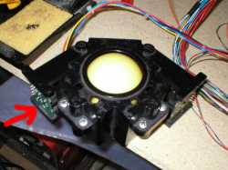
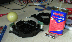
Pictured right is an Atari trackball from a Centipede game, this i am
going to use, so that i can convert Crystal castles
and Missile Command to Jamma and play them
in my 26" Jamma cab. This is how i have the trackball sat in front
of me, for co-ordination of layout, with the opto pcb's facing me, so
if i mention left hand side (arrow'd) or
right hand side, you understand where on the enclosure i am on about.
|
|
|
Optical
wheels and loom connectors.
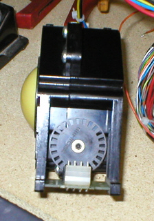
Turning
the enclosure on its side (so that the right encoding
wheel is facing you)
you
will clearly see the wheel with its windows, in front of this, is a
molex type connector which has 4 pins, with the trackball in this position,
i number these pins from left to right : 1, 2,
3, 4 . So this is the Right hand connector and
the wiring for this is as follows :
Pin 1 = Horizontal
CLK
Pin 2 =5V+
Pin 3 =GND
Pin 4 = Horizontal
DIR
Now
turning the enclosure on its other side (so the
left encoding wheel is facing you) i again number these pins
from left to right : 1, 2, 3, 4 .
So this is the Left hand connector and the wiring for this is as follows
:
Pin 1
= Vertical CLK
Pin 2 =5V+
Pin 3 =GND
Pin 4 = Vertical
DIR
|
|
|
Dismantling
Trackball.
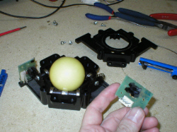
The Enclosure
itself comes in 2 halves, a top part and a bottom part. It is held together
with 6 phillips headed screws, simply undo these and the top part of
the enclosure can be lifted off. It is now possible to access all the
internal components. Here i have lifted out the left optical coupler/pcb.
N.B. In this pic i have turned the trackball assembly
around, so in my hand i have the left optical coupler/pcb and not the
right one which is still in situ...
|
|
|
Optical
coupler cleaning.
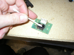
Once the optical
pcb has been lifted out it can be cleaned, 8 times out of 10 a non working
optical coupler is down to it being dirty, as dust and grime builds
up on the surface of the optic.
I found the best way to clean it, was to use a dry cotton bud and gently
rub it in the center slot of the optical coupler.
After that i gave the whole thing a good blast with my air duster can
( Maplins order code UP76H)
|
|
|
Bearings,
Rollers and lube.
The bearings and rollers are obviously what give the rollerball its
smooth action, so if yours is stiff, awkward to move or noisey, then
these need to be looked at and either lubricated or replaced. On the
bearings themselves i used regular 3 in 1 multi lube, so that they spin
nice and smoothly.
|
|
|
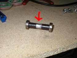
Bearings
and Rollers.
The rollers
themselves may have wear to the middle (where
the ball comes in contact) small wear of 1mm to 2mm is o.k. but
anything like the roller pictured (arrow shows
excess wear) should really be replaced with a new one. Trackball
kits are available from Arcadeshop
Amusements in the United states and are nicely priced at $20
for a complete kit of rollers and bearings or you can buy just the rollers
for $10. This is a very
wise investment as it makes your trackball run silky smooth once again.
|
|
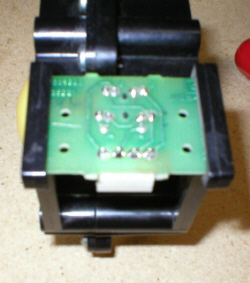
Soldered
joints.
On
the back of the optical pcb's are obviously the soldered joints, these
can have cracks or pits in them and not be making a proper circuit.
So it pays to reflow these with some fresh solder. Using a 15 to 18
watt soldering iron and a solder sucker or solder braid, remove the
old solder from one pin and then reflow in some fresh solder, do this
in turn to all the pins on the optical pcb.
Once you have done this to both of the optical pcb's, you are now
ready to try out your work by replacing it the game and using it.
If you still find after all this that the track ball still doesnt
work, you will need to replace either or both of the optical couplers.
|
|