
![]()
|
|
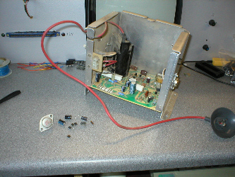 |
Wells Gardner 6100 monitor HV cage cont... Turning
the unit over to unsolder the faulty components showed more signs
of burning to the pcb. So i fitted one of my WG6100
rebuild kits available here
and replaced the following: Capacitor C902 was actually bulging !! |
![]()
 |
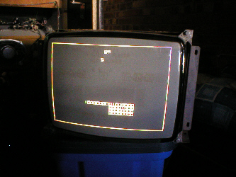
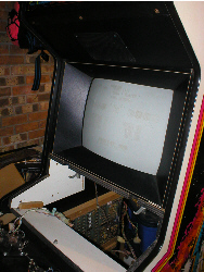
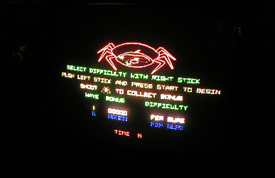
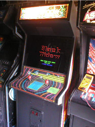
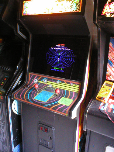
Testing Monitor before fitting. Once i had made all the necessary repairs to the HV pcb it was a matter of fitting it back on the monitor frame, plugging the monitor in and trying it, but the spot killer LED on the Deflection pcb came on suggesting there was a fault, so i flicked the switch inside the cab that puts the game into test mode to ON and the spot killer LED went out, looking at the screen showed the first part of the test sequence was up and indicating that both the Pokeys on the game pcb were dead or their sockets were bad and that there was a bad Rom 5 or its socket was bad also. |
 |
![]()
|
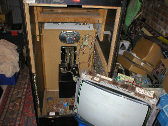
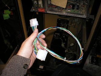
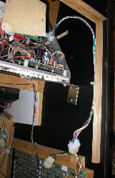
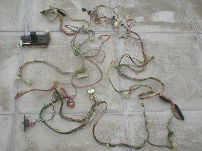
Missing monitor loom . Now
that i knew
the monitor was working ok it was time to fit it back in the cab,
but upon placing it in position it was obvious that the monitor plug
on the loom was not going to reach the monitor socket on the side
of the monitor cage. The picture on the right shows the plug and socket
arrow'd in Red, so there was obviously a bit of loom missing, asking
around other collectors that have Gravitars
and Black Widows and i was told
that there is in fact a monitor extension loom. Rather than try and
source one of these i decided to make my own. The orginal loom would
of been made up from a "Mate-N-Lok" style plug and socket
and 14 wires. 11 wires were 16 x 0.2mm 3 amp
stranded in: The 3 amp wire i had in correct colours, but the 5 amp i only had in Brown and Blue, so the Blue substituted what should of been Grey. |
 |
![]()
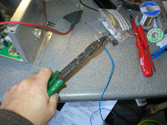 |
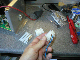
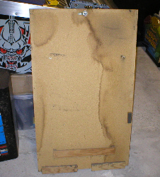
Monitor loom build. First i order'd a 15 pin "Mate-N-Lok" plug and socket plus male and female pins, but 20 of each instead of 15, that way if you make any mistakes, you have spare pins ! I then cut off 2' lengths of each of the colours of wire i needed, stripped the ends, twisted the strands and crimped on a pin for the "plug" type connector, then clipped them into the plug, i started with the thicker wires first and just copied the layout of the connector already in the cab. * Crimper used is for uninsulated terminals. |
 |
![]()
 |
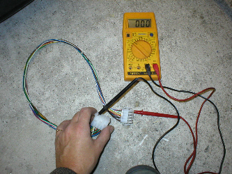
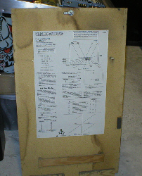
Monitor loom build cont... It
was then a case of stripping the wires at the other end, twisitng
the strands and crimping on the pins for the "socket" type
connector and clipping the pins into the socket connector in a matching
order to the plug end, once i had done this i tidied up the new loom
with some cable ties, once complete i got out a multi meter and con
checked the loom pin for pin for continuity 1.
To make sure all the pins were making good contact with the wires. |
 |
![]()
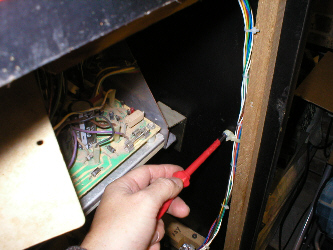 |
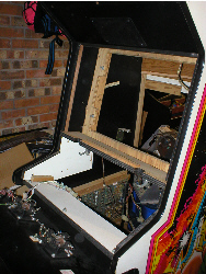
Attatching to the Cab. With
the loom made it was time to fit it to the cab, to make it fit like
it would have from the factory, i found an old atari loom kicking
around in one of the parts boxes and with a small flatbladed screwdriver
managed to unclip a cable tie type fastener, these are like a regular
cable tie except they have a ringed end so you can fasten it to wood
with a self tapping screw. |
 |
![]()
 |
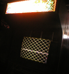
Fitting Monitor.
|
 |
![]()
 |
|
 |
![]()
 |
|
![]()
 |
|
 |
![]()
 |
 |
![]()
 |
 |
![]()
![]()