
|
|
|
|
|

![]()
 |
![]()
|
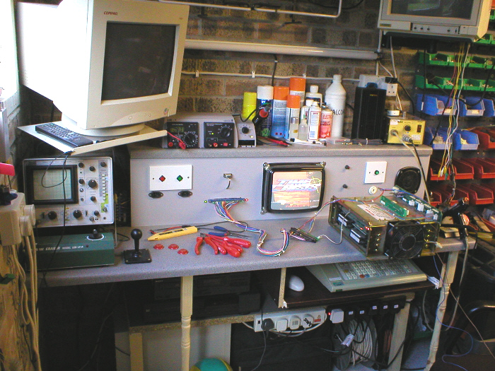
This page is where i list repairs i have done to any of my game boardsets, the reason i started to have a go at repairing my pcb's was because i was getting fed up with buying untested boards and them being faulty / dead. In
the begining i only used the basic tools |
![]()
|
Pinx's
Repair Logs.
! All notes here are for reference only, i will not be held responsible for any mistakes / damage done to your pcb's ! |
|
Pcb
|
Fault
|
Action
taken
|
|
Arknoid
(Taito pcb) |
Dead,
completely blank screen and no sound.
|
Cleaned
edge connector with a rubber, still dead, checked for touching pins,
found 3 dry joints, re-soldered these, still dead. Replaced the Z80
processor with a known working one, nothing. So then checked pcb for
5v+ and 12v+.
It had 12v but no 5v.
Traced back right through to edge con and jamma adapter and then to
jamma con itself (inside cab) and found
one of the 5v wires was missing. Tried
pcb on test rig. Worked perfectly. That'll
teach me to be lazy !!
|
|
Asteroids
(Atari) |
Marquee
would light up, but no game. No 5V+ at game pcb and LED on Deflection
pcb was on, so spot killer was activated.
|
As
i had no 5V+ i looked at the AR1 (Audio
Reg pcb) first, i replaced all the capacitors at C1,C4,C12
(470mfd 25V) and C13
(1000mfd 25V)
and C9,C10 (3300mfd
35V) i then meter'd the transistors and found the TIP32
at Q2 to be dead, so i replaced this with
a 2N6107 (better
rated component) This brought back the 5V+
and the game would then play ok.
|
|
Asteroids
(Atari) |
Game
would play but was just a horizontal line across the screen, no "Y"
Axis.
(GO5/801 monitor) |
This
problem had to be something to do with the Deflection pcb or its large
transistors mounted on a seperate heatsink just above the Deflection
pcb, so i started by metering the transistors Q607
(2N3792) and Q608
(2N3716) located on the large heatsink,
they meter'd ok, but due to there age 25 years
old ! i replaced
them anyway, in fact i did the "X" Axis too. I then removed
the Deflection pcb and started metering the components in the "Y"
section and found the transistor at Q601
(TIS98) and the axial lead fuse at F600
(2 Amp Pico Fuse) to be dead, so i replaced
both of these, game then worked ok.
|
|
Bomb
Jack
(Tehkan) |
Black
screen with the odd flecks of colour.
|
The
game runs with 2 clocks (crystals) a 4.000 mhz at J4
and a 12.000mhz one at between T4 and T5,
using a logic probe, i checked the J4 one
for a pulse and this was fine, but probing the one at T4
/ T5 caused the game to boot up and play
ok. The only thing i could think of was that either of the two capacitors
in that circuit were leaky, so i replaced both the 103Z
and 221J caps at T4
and this cured the problem.
|
|
Bomb
Jack
(Tehkan) |
After
only 3 or 4 minutes of playing the sound would deteriorate untill there
was no sound.
|
The
first thing i did was touch the amp to see if it was getting very hot
and it was, but as soon as i did this, the coolness of my fingers made
the sound work again, so i used some freeze spray on it and it made
the sound last 6 or 7 minutes. So at first i added 2 small heatsinks
to the amp, this made the sound last for 15 minutes or so. In the end
i replaced the M151516 amp and this fixed
the problem.
|
|
Defender
(Williams) |
When
turning on, the game would just stay in rug pattern, continuosly.
|
Located
the 5101 CMOS Ram on the CPU pcb removed
the old chip, which was solder'd straight to the board and replaced
it with a socket and new 5101 chip, this
then got the game to finish rug do its initial tests and go into book
keeping.
|
|
Defender
(Williams) |
Game
would not exit book keeping.
|
This
problem is normally related to the 5101 CMOS
Ram but as i had replaced and socketed this already, it had to be something
else in the memory backup circuit, so i replaced the 4071
CMOS that runs in conjunction with the 5101
and Bingo! the game would leave book keeping and go into attract, at
this time i also performed the lithium battery conversion detailed later
on this page, to further aid reliability.
|
|
Defender
(Williams) |
Game
would play for about 5 mins but would either freeze or crash and go
back into rug pattern.
|
This
problem had me baffled for ages and i origionally thought it was a 4116
Ram problem, but after replacing all the 4116's,
it still did it, so i started to look at the power supply instead (as
i was still using the origional linear one) using a scope on
the VDC lines, it showed that the PSU was suffering from ripple, so
i performed a Bob
Roberts rebuild kit on it (re-cap and
IC replacement) and this cured the problem.
|
|
Defender
(Williams) |
Game
would play in attract mode, could be coined up, but couldnt be started.
|
Went
into book keeping and put the game into test mode, failed test in the
control section and came up with "invalid
switch1" which scrolled down the screen, so it had to be
a problem with the widget (interface) board.
I removed this from the cab and imediately replaced the PIA
with a socket and a new chip, but this did nothing, i then replaced
and socketed all the logic IC's: 3 x 4049 (cmos)
and 2 x 74ls257 this then
fixed the problem.
I later tried the removed chips in a friends ic tester and it showed that one of the 74ls257's was duff so the other chips were kept for spares. |
|
Eagle
(Centuri pcb) |
Game
would play, but would not sync properly and had no sound.
|
After
checking edge con, it looked as though speaker- didnt actually go anywhere
on the board (pin v parts side), so i connected
speaker- on the adapter loom just to ground instead and the sound worked.
On the back of one of the pcb's there were some white jumper leads, a cut track, a chip with 2 pins soldered together (solder side) and one of the wires went to a chip that had one of its legs snipped. This turned out to be a hack to make the game positive sync. Removing the jumper wires, repairing the cut track, de-soldering the joint pins and re-soldering them seperately and re-connecting the snipped leg with a blob of solder, reverted the game back to negative sync and then the game would sync properly. |
|
Exerion
(Jaleco/Taito) |
Game
plays with sound but has 3 faults, jailbar effect in sprites, any explosion
leaves one of the alien sprites on the screen and finally the background
terrain is all spikey.
|
Started
by pressing all eproms and found that pressing eprom
9 at L11 would cause
the jailbar effect to come and go, removing the socket and replacing
it fixed this problem.
Upon inspecting the tracks i found a break on the component side at U11 / U12 adding a small jumper wire across this break fixed the explosion / sprite problem. Lastly i found another break in a track at V8, adding a small jumper wire across this break, fixed the spikey terrain problem, pcb now works 100%. |
|
Exerion
#2
(Jaleco/Taito) |
Dead
pcb, no video output, nothing.
(This pcb is a Jaleco one, not the taito mention'd earlier) |
Most
obvious thing, was the fact that both Z80's
were missing, just a couple of empty sockets, fitted 2 x Z80,
still nothing, so i checked the crystal (clock) at A1
and found no pulse, replaced the 20mhz
crystal and this brought the video back, leaving a nice screen of yellow
/ red blocks.
|
|
Exerion
#2
(Jaleco/Taito) |
Screen
of static yellow / red blocks.
|
Started
by removing all the eproms and trying them in my spare pcb and they
worked, so that ruled those out of the equasion. Took out Z80
#1 an hooked the pcb up to the Fluke 9010A, this told me that there
was something wrong with the address lines, so i set a multi meter to
continuity "bleep test" and bleep'd all the pins on both Z80's,
Z80 #1at R5 / R6
had no contact on 3 pins, so i replaced the socket with a new turned
pin one. This then gave the yellow / red blocks flicker in some of the
pixels.
|
|
Exerion
#2
(Jaleco/Taito) |
Screen
of static yellow / red blocks
|
Tracked
around the pcb with the logic probe looking for missing signals and
found 74ls193 counters at 10R
and 10T were missing some outputs, so i
replaced both of these, which then got a signal to the 74ls138
at 10U but this had no outputs, so i replaced
this too.
The 74ls193 at 10R also feeds the 2114 Ram located at 11R and 11S, these both turned out to be duff and so did a 6116 wide body Ram at 6N, replaced and socketed all of these. Now i had a corrupt static Title screen, but you could make out the word Exerion, so i was getting somewhere... |
|
Exerion
#2
(Jaleco/Taito) |
Corrupt
static Title screen, but you could make out the word Exerion.
|
Carrying
on with the probe i found that some of the 74ls374's
on the pcb had no clock signal @ pin 11
and the chips effected were all in one area, checking the schematics,
i found these to be fed by a 74ls74 at
9F which was duff, so i replaced and socketed
this, clock pulse was now back @ pin 11
of the 74ls374's, but still the same fault.
|
|
Exerion
#2
(Jaleco/Taito) |
Corrupt
static Title screen, but you could make out the word Exerion.
|
Whilst
probing other parts of the pcb i had leant on a bank of 8
93425 (2125)
Ram and found these to be very hot and i mean almost untouchable, i
used freeze spray on these, which made no effect, but found they would
be hot in seconds. Two of these Ram were socketed and looked like an
earlier repair of some kind, both of these were missing an output @
pin 6. By removing the sockets i found
broken tracks underneath, that went to both these pins, so i added jumper
wires on the solder side of the pcb. This then brought back the signal.
|
|
Galaxian
(Sub Electro pcb) Parts and layout mostly identical to an origional |
No
sound, not even humming.
|
Replaced
volume pot with another 10k one, but still nothing, touched pins on
back of amp, whilst powered up but no humming, checked 12
volt feed to amp chip (LM380N) located
@ L14 or C10
on an origional pcb, with a multimeter, feed was o.k. so replaced amp
with new chip. Sound then worked.
|
|
Galaxian
(Sub Electro pcb) Parts and layout mostly identical to an origional |
Starfield
would work o.k. |
Worked
my way around the pcb pressing the socketed ram and logic, whilst powered
up, pressing chip (74LS74pc) located @
B13 or D2
on an origional pcb, made Starfield come and go. Unsoldered socket,
that chip was in and re-soldered in a new one. Starfield then worked
constantly.
|
|
Galaxian
(Miday pcb) |
Game
would play fine, but when the invaders would dive, they would flash
on and off.
|
With
the game powered up, i moved around the board pressing any socketed
ram, i found that pressing the 27LS00 attack
ram chips located @ P1 and
N1 would stop the fault happening, i couldnt decide
which chip was actually doing it, so i just replaced both the sockets
on these ram. This solved the problem. There are 5 of these attack ram
in row 1 and they tend to get very hot, a tip i got from a friend (Cheers
Phil "Degauss") was to
attatch small heatsinks to them.
|
|
Gyruss
(Konami pcb) |
Game
would re-boot at any time for no reason, or would be dead on start up
if pcb had just been put in cab.
|
This
sounded like there was some kind of loose conection on the pcb's or
on the connectors between them, moving around the boards pressing things
made no difference,cleaned and re-connected the ribbons but nothing,
then i noticed a really bodged repair (ugly blobbed
solder) on a crystal located @ G19
on the bottom pcb so that one of the legs had a bad joint, removing
and replacing this crystal fixed the problem.
|
|
Hyper
Olympics
(Konami pcb) |
Game
would play fine, but highest scores would have corruption in them if
dips were set for save scores. But o.k. if dips set for not save scores
|
As
the score save option requires a battery to keep the memory active,
i checked this first, its a button cell type battery and it was dead.
I managed to get an equivalent replacement and fitted that. This solved
the problem and stopped the corrption.
(I should think this will also work for Hyper Sports) |
|
Mr
Do's Castle
(Bootleg of Universal) Parts and layout mostly identical to an origional |
Bootleg
pcb, that just had a screen of moving corruption
(identical to origional except for a missing custom chip) (that has a daughter card in its place.) |
Moving
corruption, pressed all socketed chips, nothing, lifted off daughter
card located @ 5F / 5H
and noticed that near it @ 7P there was
an empty socket, checking the schematics showed that there should of
been a 2128 (6116) Ram in it. Replacing
this missing chip, brought the game straight up and i could coin it,
but when you pressed player 1 the game would start but in 2 seconds
would go to level 2 and in another 2 seconds go to level 3 and in another
2 seconds level 4 and so on. This had me baffled for ages, but in the
end turned out to be a dip switch setting. Dip switch
6 is for Automatic screen renewal and it was in the wrong position,
changed the setting and game worked perfect.
|
|
Pacman
(Midway pcb) |
Just static garbage on screen.
|
This
was my first Pacman repair so before making an adapter and plugging
it in i did a visual inspection of the pcb and found 3 chips in sockets
the wrong way round ! These were a 2114
Ram @ 4K a Prom
@ 4A and another Prom
@ 3B, i also notice that
the Z80 @ 6B
was missing and also a chip @ 6D was
missing too. I replaced the Z80
and put the chips back in the right way round, made an adapter and fired
it up on the rig, all i had was static garbage on the screen, i figured
the missing chip @ 6D couldnt be helping
this so, so i looked at schematics on the net and found it to be a custom
sync bus controller for the Z80, according
to the schems you could also use a daughter card A082-91383-B000,
so i sourced one of these and fitted it, this then gave me a screen
of white zero's, so i decided to look at the Ram first, taking the 2114
out one at a time and testing them, showed there to be dead 2114's
@ 4K and 4R,
so i changed these, but still the same problem, i then meter'd the sockets
on continuity and found bad sockets @ 4P
and 4N, so i replaced these also and the
game then sprang into life, but had no sprites. At this point it was
obvious that the pcb was actually a Miss Pacman.
|
|
Ms
Pacman
(Midway pcb) |
Game
looks to be playing but has no sprites, you can see dots dissapear,
but no Pacman or Ghosts.
|
The memory used for the sprites are located @ 2A, 2B, 2C, 2D and they are 2125 (93425) RAM, so i took a look here first, all the chips had heatsinks on them (as they get very hot) except one, which looked like it had been knocked off, so i removed them all fitted sockets and tested them one by one and oddly enough the one with the missing heatsink was duff, so i replaced this @ 2A, this brought the sprites back and it would sit and play in attract mode. Picking up the pcb to look at it, made them come and go though, i moved around the pcb tapping it in places and the sprites would come and go, i then worked out that by gently flexing one corner of the pcb (A1 corner) i could get the sprites to show, i started tapping on chips, but this had no effect in the end i started pressing on the resistor network at RM4 and this seemed to be the cause, replacing this with a new 10 pin 1K resistor network cured the problem. |
|
|
The
game played fine but was missing some sounds, music was there and most
of the other sounds, but there was no fire or ship explosion sound.
|
Did
the usual trick of pressing socketed chips, but with no luck, then with
the game running i checked out the 555
timers with the logic probe and found that the output of the chip (555
timer) @ IC42 was stuck high. Removing
this chip and replacing it solved the problem.
|
|
Space Invaders (Taito) |
Game
played fine but had lots of missing sounds.
|
Looking at the schematics i saw that the sound pcb used seven quad amps for the sounds @ 2E, 2G, 4D, 4E, 41, 4J, 1H and so i replaced all these first, this then gave me all the sounds except the Base hit sound and the Base fire sound, looking again at the schematics i saw that in the same circuit, there was a 74174 D-Type flip flop @ IC15 and a 4006 Cmos IC24 and also a 556 timer @ IC17. The 74174 had no output at pin 5 so i replaced this first, this gave me an output at pin 5 but still no sound, so i then replaced the 4006 and this brought back the shoot sound though it didnt sound quite right, so i replaced the 556 timer and this returned the fire sound back to normal. Replacing that timer also made the Base hit sound appear as just a loud click. I meter'd all the resistors in this circuit but they all turned out to be ok, so i then turned my attention to all the 104K Mylar capacitors, positioned in between the amps and the two Mylars located near the 4006, replacing all of these brought back the Base hit sound. |
|
Space
Invaders
(Taito) |
Black
and White pt 2 cabinet, lost its black level so
background was grey. (Toei monitor) |
Game
played as normal but the black area's of the screen were grey, winding
the contrast right over brang it back to black but put the image out
of focus which couldnt be adjusted. First i re-capped all the electrolytic
radial capacitors on the chasis as they were origional from 1979 ! This
had no effect, so i then meter'd all the transisotrs on the chasis but
they were ok. I couldnt find any schematics for this model monitor so
i started lifting legs on resitors and metering them out of circuit
and found a 680K resistor @ R61
was giving no reading, following the pcb tracks it looked like the contrast
and focus circuits were somehow combined and this resistor was in that
circuit. Replacing that resistor fixed the problem.
|
|
Typhoon
(Konami) |
Bought
of Ebay as a worker,
but was just re-setting corruption garbage. |
Hooked
it up on the test bench and it was just random moving corruption that
would reset about every 5 seconds, the pcb was very dirty, thick with
dust, so i removed all the eproms and anything else that was socketed
and re-seated them all, this gave me half a test srceen saying it was
checking ram, but the other half of the screen was still garbage. I
then cleaned between the legs on the 3 surface mount chips with a tooth
brush and some pcb cleaner/flux remover. This then gave me a full test
mode screen, which was saying it had a bad Rom at G16
and still it would reset about every 5 seconds, so i started gently
flexing the pcb and on one of its 5 second resets it passed the self
test and booted into the game, but with blocks of corruption in the
background, i then started pressing Rom G16
and it made the corruption go, so i removed the old socket, fitted a
new turned pin type socket, cleaned the legs on the Rom and Bingo it
worked.
|
|
|
|
|
|
|
|
|
|
|
|
![]()
|
Basic Repairs. These are basic things that anyone can try, they dont always work, but sometimes they do, so as it costs nothing to try, its worth having a go and you dont have to be Einstein to do them either..... ! All notes here are for reference only, i will not be held responsible for any mistakes / damage done to your pcb's ! |
|
Component
|
Photo
|
Action
taken
|
|
Pcb
Edge Connector
|
 |
These
over time build up a film of grime that is almost invisible to the naked
eye, so get a nice large pencil rubber and give it a good rub on both
sides of the edge con.
|
|
Power
supply
|
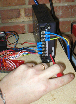 |
On
most power supplys (p.s.u) there is a 5V+
trim adjusment. Using a small screwdriver move this until you are getting
exactly 5V
(measuring with a multimeter) at the edge con. Some pcb's, bootlegs in particular dont like running at voltages under 5V, some bootlegs wont even work unless the voltage is slightly higher than 5V. Symptoms can be dead boards or corrupt graphics or pixel flicker. |
|
Socketed Chips
Ram, Rom, Prom, Eprom |
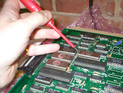 |
Bad
connections from socketed chips can cause a multitude of problems, so
being very carefull not to bend or break any legs, carefully prise out
a chip by levering from each side, a little bit at a time alternating
as you go. Then carefully replace it back in its socket, taking extra
care not to bend any legs and remembering to put it back in the socket
the correct way round ! (chips have a notch at
one end, make note of this before removal) Do this in turn to
each socketed chip and only do one at a time, that way you wont get
any chips mixed up..
|
|
Soldered joints
|
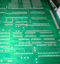 |
If
you turn a Pcb over, all the pins / legs call them what you will,
come through holes in the Pcb and are attatched with a little blob
of solder. Some pins maybe a bit longer than others and if kept in
bad storage |
![]()
![]()
|
Click
banner for Home.
|